Impex GD-810 Owner's Manual
Browse online or download Owner's Manual for Unknown Impex GD-810. Impex GD-810 Owner's Manual User Manual
- Page / 14
- Table of contents
- BOOKMARKS
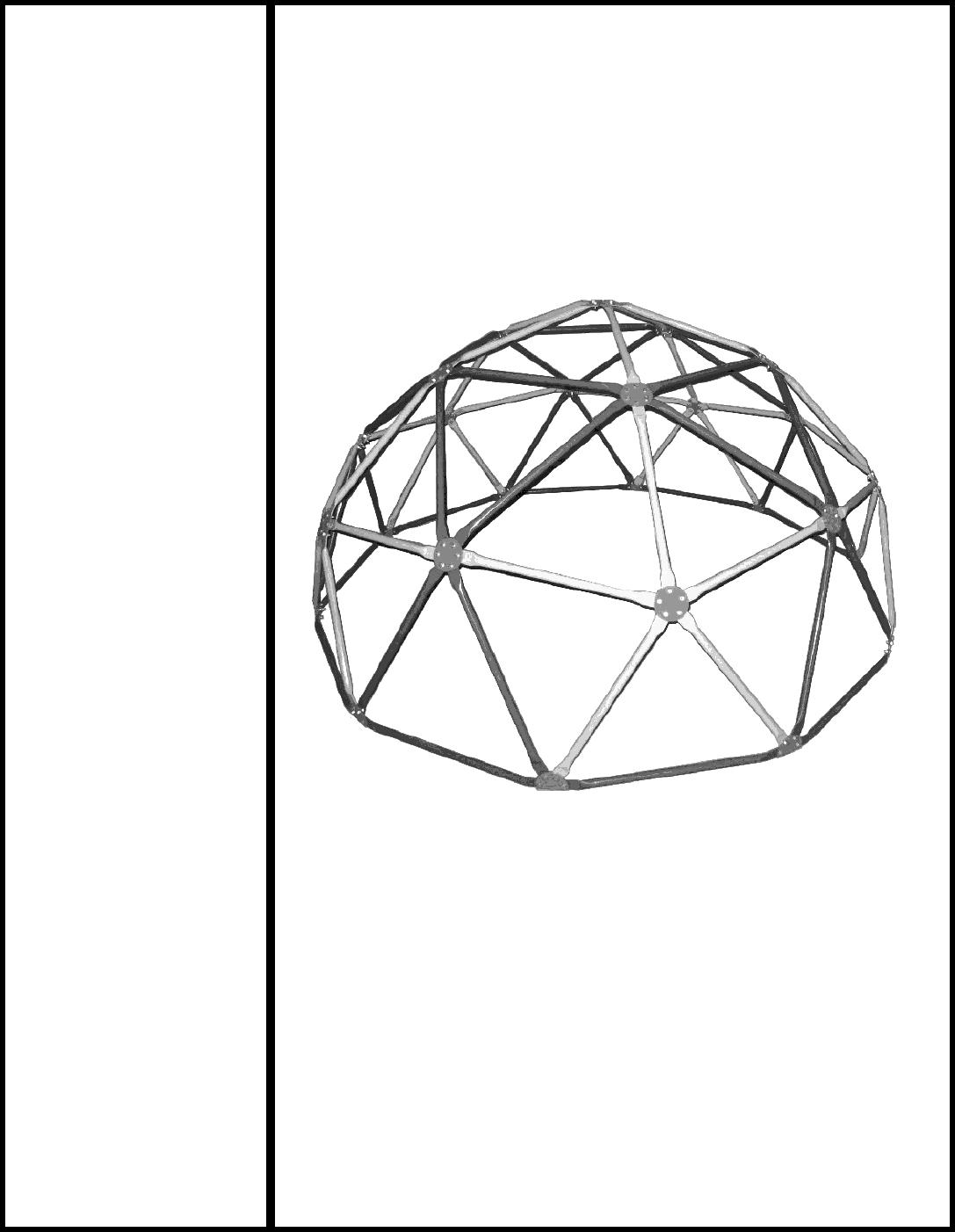
- SPACE DOME 1
- IMPORTANT SAFETY NOTICE 4
- HARDWARE IDENTIFIER 6
- DIAGRAM 1 7
- ASSEMBLY INSTRUCTION 7
- DIAGRAM 2 8
- DIAGRAM 3 9
- DIAGRAM 4 10
- DIAGRAM 5 11
- EXPLODED DIAGRAM 12
- Parts list 13
- LIMITED WARRANTY 14
Summary of Contents
NOTE: Please read all instructions carefully before using this product Table of Contents Safety Notice Hardware Identifier Assembly Instructio
Step 4 (See Diagram 4) A.) Connect two lower beams on a Frame-A (Blue) to the 4-hole Brackets (#3) on Frame-C. B.) Secure each hole with one M8 x 5/8
Step 5 (See Diagram 5) A.) You should have five Blue Frames (#1) left by now. B.) Connect the five Blue Frames (#1) horizontally to the opening holes
EXPLODED DIAGRAM 11
Parts list KEY NO. DESCRIPTION Q’ty 1 Blue Frame 35 2 Yellow Frame 30 3 4-hole Bracket 10 4 5-hole Bracket 6 5 6-hole Bracket
IMPEX® INC. LIMITED WARRANTY IMPEX INC ("IMPEX®") warrants this product to be free from defects in workmanship and material, under normal
TABLE OF CONTENTS BEFORE YOU BEGIN... 1 IMPORTANT SA
WARNING LABEL PLACEMENT The warning label shown here has been placed on the frame. If the label is missing or illegible, please call customer s
IMPORTANT SAFETY NOTICE This play ground equipment is built for optimum safety. However, certain precautions apply whenever you operate a piece of pl
CONSUMER INFORMATION SHEET FOR PLAYGROUND SURFACING MATERIALS The U.S. Consumer Product Safety Commission (CPSC) estimates that about 100,000 play
HARDWARE IDENTIFIER 5
ASSEMBLY INSTRUCTION Tools Required Assembling the Machine: One Adjustable Wrench and one Allen Wrench NOTE: It is strongly recommended two or more
Step 2 (See Diagram 2) A.) Attach five Yellow Frames (#2) to a 5-hole Bracket (#4). B.) Secure each Yellow Frame to the Bracket with one M8 x 5/8
Step 3 (See Diagram 3) A.) Connect a Blue Frame (#1) to a 4-hole Bracket (#3) and secure them with one M8 x 5/8” Allen Bolt (#6), Ø 5/8” Washer (#7
Related products and manuals for Unknown Impex GD-810
 (8 pages)
 (15 pages)
© 2020, manymanuals.com. All rights reserved. | 0.075 s |
 Manymanuals.com
 Manymanuals.de
 Manymanuals.fr
 Manymanuals.it
 Manymanuals.pl
 Manymanuals.cz
 Manymanuals.es
 Manymanuals-pt.com
Comments to this Manuals